4A-GE Camshafts
Submitted By Richard White, revised 4/19/2000
Modification of an engine’s valve timing is best approached with a degree of caution. For otherwise stock engines, the mildest cams should perform well. Performance will improve with improved induction, i.e., carburetion or a more efficient injection (ported/polished throttle body) and exhaust system (headers). Modest performance increases can always be achieved by fine turning with adjustable timing gears to advance or retard the valve opening and closing.
In discussing and comparing camshaft designs, there are three important parameters to keep in mind. First is the lift, or how far the valve comes off the seat. Unfortunately we seem to forget from time to time that there is theoretical valve lift and net valve lift, and because the 4A-G is an over head cam design there is little difference between the two. The camshaft acts directly on the valves through the shim and bucket (lifter, follower).
The second important parameter, is the duration. This is the length of time, measured in crank degrees, that the valve is open. There are usually two methods of stating this measurement. Advertised duration is normally what you see when looking at a catalog and the second method is usually stated at some point in the valve lift height. (None of the major suppliers for the 4A-G do this for reasons unknown). Thus directly comparing one camshafts duration against another would only be useful for comparing camshafts from the same manufacturer.
The last parameter to keep in mind is where to set the camshaft. It can be set by the beginning of the valve opening or closing or at maximum lift, lobe center. The lobe center is usually between the opening and closing angle, but not necessarily so, especially if the opening and closing ramps are not symmetrical to each other.
Depending on how fast the valve is lifted, the high lift cams (generally recommended for 9mm and up) require under bucket shims to keep metal pieces in their proper spot. If cylinder filling capacity is the same between a seemingly long duration cam and a high lift cam, a fat, flat top cam lobe, not having very much lift may try an aggressive (square shape), valve opening and closing. This is to try and gain the advantage of increased flow by allowing the valve to open sooner and close later, which can result in tremendous stress on the cam and lifters. On the other hand, a pointy Hi-lift cam may have reduced stresses to the lifter but may increase stress to the valve spring to the point of binding the spring. As a practical matter there is a point at which increasing lift has little benefit in increasing efficiency and is obviously depended upon operating RPM. Therefore the design of each valve train component is dependent on a cam feature. The valve spring is affected by the lobe height, and the lifter & shim is affected by the cam ramp and/or flank.
The area on the cam lobe that determines the rate the valves open and close is the ramp. The ramp is that part of the lobe that takes up or allows the re-establishment of clearance in the valve train. Ramp designs have a great effect on throttle response, low speed torque, and valve train reliability. This is the hardest to measure and usually not published. The Ramp design separates manufacturer's designs from another. Moreover, the duration and lift are usually advertised numbers and are not necessary a good way to compare one design to another. The .9835” diameter of the shim will only allow so much aggressively quick opening before the cam lobe catches the edge of the shim or is popped out of the lifter like a tidily wink. An under bucket shim configuration will allow added safety by protecting the shim and allowing greater contact area, e.g., ~ 1.102” dia. of the lifter (bucket). Though it is more time consuming in setting and maintaining the proper valve lash, clearance.
Note, when measuring a cam profile the area of contact between the cam lobe and the lifter, i.e., the width of the shim, has a profound affect on the rate of change (crank degrees per inches (mm) of valve Lift) the valve and valve train will under go. So if your are calculating loads and acceleration of the valve train, it is best to measure crank degree change per lift with a wide flat surface, simulating the lifter, rather than using just the point of the dial indicator. This would give you a better indication of the cam’s actual duration.
The larger the duration and lift a camshaft has, the more it becomes necessary to have a better induction and an exhaust system. Since the engine is an air/fuel pump and the more air/fuel you can pump into it on any given stroke the more potential power you can gain. Higher lift allows for potentially more air to flow, while increasing the duration allows the air/fuel to rush in longer. Notice that I have used the words “potentially”. This is because efficiency depends on what is before and after the valve, not to mention the valves themselves. The more radical cams require higher compression pistons and greater valve spring clearances and/or spring rates for higher lift, and preventing valve float. A camshaft is part of the induction system and it must be tuned with all the other components within that system to work to its full potential.
The cam designer wants to design a cam that will open the valve as quickly as possible and hold it open as long as needed for cylinder filling and close the valve at the correct time and in the process keep all of the metal pieces intact. Cam grinders and racing engine builders are seeking a rectangular valve lift profile. This is an ideal that cannot be approached, but if it could the valve would remain closed until you wanted it open and then it would be fully opened instantaneously. It would be held there for complete cylinder filling, and then it would be closed instantaneously. The height, lift, of the valve opening would be the height that the flow bench or trial and error showed would produce the desired maximum amount of filling.
In reality, the cam must be designed to open valves before the piston starts a stroke and it also must close the valves after the completion of the stroke. The intake charge can be visualized as being “parked” in the port waiting for the valve to open. As the valve opens further, the velocity of the intake charge grows. Opening the intake valve before the piston ever reaches TDC (top dead center) the cam designer is already taking advantage of the situation and allowing the intake system to build up a maximum amount of velocity or inertia to aid in cylinder filling. As the piston goes over TDC and starts downward, the velocity of the air/fuel mixture increases as the intake valve reaches maximum lift. Even after the piston reaches BDC (bottom dead center) and starts back up on the compression stroke the intake valve is still open, allowing more air/fuel to enter. The compression stroke does not develop enough pressure against the incoming mixture flow to interfere with this flow until the piston is part of the way up the stroke. It is said that the intake charge has inertia.
On the exhaust side, the valve is opened long before the end of the power stroke. In theory it would be nice to keep the intake and exhaust valve closed until the piston reaches the very end of the power stroke to take advantage of all of the pressure created by the combustion. In practice, the bit of burning gases that are left is not worth fooling with since the peak cylinder pressure is over before the halfway point of the stroke (discounting emissions). By opening the exhaust valve early, the velocity in the exhaust port can begin to exit and thus the piston on the next upward stroke will not have to fight to get the exhaust gases past the valve and into the port. The exhaust valve is left slightly open as the piston is once again brought up to top dead center. This is done to help scavenge as much of the residual gas as possible still in the combustion chamber.
In a typical turbo set-up, they will run relatively short duration (less over lap) cams. Otherwise they will blow all the intake charge into the exhaust side, or worse, reversing (reversion) the exhaust gas into the intake. The pressure, intake or exhaust, will find the easiest path to flow, and if it is easier to go straight through the cylinder, equalizing the difference in pressure and decreasing the amount of work the turbine can do, it will. You will not only lose the air/fuel charge that could have gone into the cylinder but decrease the efficiency of the exhaust turbine as well. The typical GSR turbo-charge Honda is running lobe centers (max lift) between 112 and 108 degrees, with 235° VTEC duration above 4,000 RPM.
On the other hand a 4A-GZE runs a positive displacement “air pump” that is dependent upon the motors RPM and not the hot exhaust gases that a turbo motor would depend upon. So increasing the duration and lift for that engine could have some benefits. It just thinks it is below sea level any way. (running at higher atmospheric pressures)
An interesting aspect of cam duration is the use of a dual pattern or different duration cams for the exhaust and intake. When used correctly, a different exhaust duration from the intake can broaden the torque range, but generally speaking they will not deliver as much peak torque as can be found with matched cams in a narrower RPM range. This is not all bad because it is still torque that wins races. Typically you will see the exhaust cam one step lower in duration than the intake to broaden the torque range, but I have not seen anything that says you can not do it the other way around.
Trying to select a cam duration to use for racing (or street) is going to be a compromise. With this in mind, the camshaft requirements for a road race, street or drags would be considerably different than for a super speedway event using a Formula Atlantic prepared engine where the RPM band is very narrow and/or has the use of a close ratio gear box.
One of the factors that must be weighed is the need for some balancing between intake and exhaust flow. This is governed by flow capabilities of the head and intake manifold in addition to, as said before, on the existing induction and exhaust system and on where you want the torque and horse power to be, and how flat or how limited the useful RPM range can be. Now this depends on the weight of the vehicle, momentum changes (acceleration and deceleration), gear ratios, track conditions, etc.
Generally speaking a short duration cam will produce more torque at lower RPM range. There are two reasons for this. The engine builds up more cylinder pressure and the cylinder pressure is put to work for a longer period of time. And as the duration increases the torque will move up the RPM range. Remember your engine and ignition system must be up to the task. As you can see by the following table listing numerous camshafts, a turner can choose from many different configurations, and a competitive racing program will have tested most of them.
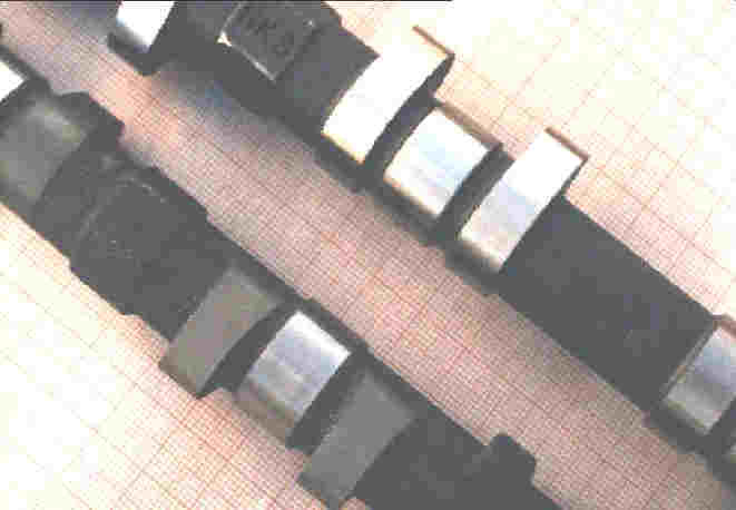
One of the many tricks that early hot rodders used to do (and still do) was to grind camshafts to the lift and duration desired. Reground stock cams have a reduced base circle which changes the valve train geometry, requiring many special mechanical modifications to make it work properly. (See Photo)
Because the 4AG has a cam lobe on either side of a cam bearing journal, it makes it critical that adequate clearance is given between the lifter (bucket) & shim and the bearing journal surface. The reduction of the cam lobe base circle, without extensive head modifications, requires the use of thicker shims. This will increase valve train reciprocating mass and inertia (adding stress and increasing the potential for major failure). Too thick a shim necessitates radiusing the edge to clear the cam bearing journal, increasing the possibility that the cam lobe will grab the shim and flip it out. An alternative would be to narrow the cam shaft bearing, but this would cause greater wear on the bearing caps and/or increase oil loss (lower oil pressure). Another alternative would be to reduce the bearing journal diameter, but that would require welding up the bearing caps and reboring them. For your information the size of the first cam bearing journal/oil seal surface should be (1.3768” ~ 1.3791” (34.97 ~ 35.03mm) dia. The journal diameters between the lobes should be 1.0610” ~ 1.0616” (26.949 ~ 26.965mm) dia.).
Therefore it is strongly urged that reground cams (Bull Frog, PAECO, etc.) not be used. Use only cams ground from new billet stock, e.g., HKS, TRD, TODA POWER, TOYOTA, etc. My suggestion is that if TRD, i.e., Formula Atlantic engine supplier, or one of the others that have extensive 4A-G racing experience do not do it, then you should be really skeptical that someone else would or does anything different. Regrinding a camshaft only removes material that the 4A-G needs to maintain the base circle the same size as the bearing journal.
With that said, it is also recommend that you follow all the recommendations the manufacturer of the cams has to offer. They have done the testing and spent the money. Typically they will also recommend changing the valve springs. The stock valve springs should not only be replaced, but also upgraded to ensure that the valves can follow the new and sometimes more radical cam lobe profile. The stock valve springs are only capable of ».318” (< 8.0mm) lift. With the stock installation height of 1.366” (34.7mm), they bind at 1.048” (26.6mm) compression and they will float some where above 8,000rpm. Nevertheless one should always check valve spring squareness, free height and installation height spring force. One should never take a chance on valve springs that do not look similar to the stock Toyota parts, or to well-established racers like TRD’s or Toda’s parts, in the number of coils, the width and height of the spring, and thickness of each coil. High performance alloy steels, heat treating, stress relieving and the most efficient coil spring design are pretty common to the industry (especially those that know 4AG).
(See Photo)

Also note that stronger springs mean greater friction and greater wear on the cam lobes and shims. It is one of those compromises that trade valve float for life. Use the best oil and filter (frequently) you can buy to make your investment last longer.
When installing the camshaft, start by following the manufacturing recommendation. For folks with a little more ambition the cam can be tuned. You will need a degree wheel and a dial indicator and knowledge of the Top Dead Center (TDC) and Bottom Dead Center (BDC) of the engine. This will establish the base line from which tests can be made and the cams advanced, retarded, separation increased or decreased as desired.
Using adjustable cam sprockets can optimize the performance of any cam. This allows for “degreeing” in the proper cam timing for the particular engine and intended use. This procedure is best carried out on a dynamometer so that quantifiable results can be measured. The advancing or retardation of cam timing will affect the peak power of the engine by moving the power band up or down the curve. There are many adjustable cam sprockets to choose from, each differing in design from all aluminum to using steel (less thermal expansion), but the most convenient to use are the ones with precision markings to allow for track turning and returning to the original settings.
In general, advancing both camshafts increases bottom-end power and retarding both cams will increase top-end by giving higher peak RPM power. On twin-cam engines, changing the lobe center separation between exhaust and intake will change the valve overlap. This can be used to improve top-end or bottom-end, but this depends on the critical placement of the intake closing and exhaust opening events. The placement of both events has a significant effect on power, i.e., exhaust valve opening determines the beginning of the exhaust cycle and cylinder blow down, and the placement of the intake closing event fixes the balance between cylinder filling and intake reversion. It must be emphasized that this is only a generalization and that you must perform dyno/track testing to fully realize the benefits. In the absence of a dyno, timed acceleration tests can be performed. These acceleration tests can also be performed using a precision accelerometer.
Tuning the cam to the specific engine operations, i.e., acceleration from a stop, between two RPM ranges, etc. will maximize what is important to you. Peak horsepower is only impressive on a dyno. By its self, it will not improve track times. Note, when adjusting the cam sprocket, make sure the ignition timing is corrected between each cam adjustment. The exhaust cam drives the distributor and any change to the exhaust cam will change the ignition timing. After changing the cam timing and correcting the ignition timing, the fuel calibration must also be checked. Cam timing has a profound effect on the air/fuel mixture and if not optimized for each cam timing setting you will not know if the effect of the change in cam timing is positive or negative.
The following list is typical literature power band information for the 4AG naturally aspirated configuration. The information is general and provides a good idea of what you can expect from the cams. The actual performance of any given cam in your engine depend on several variables including type of induction system, carburetion or fuel injection, exhaust system, valve spring rates, compression ratio and the normal environmental factors such as fuel, ambient temperature and humidity etc.
The 4AG intake and exhaust cams are interchangeable, providing that the exhaust cam has the distributor gear (not necessary for digital spark advance systems). Remember, too much cam will make the engine run worse, not better. The power will come on higher in the RPMs. Idle will be poor and emissions will be bad (if you cared).
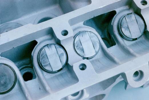
View of shims wiped by an 8.3mm lift HKS cam shows it is using all the available area. The Ramp design is critical, so that the shim edge does not catch the cam lobe. Also notice the under cut in the bearing saddle. Extra thick shims will interfere with the cam-bearing journal. Therefore it is critical the base circle of the camshaft not be less than the diameter of the cam bearing.
4A-GE 16V Camshaft Comparisons:
|
Duration |
Lift |
Intake opening |
Exhaust opening |
Comments |
|
232° |
7.1mm |
8°BTDC
|
47°BBDC
|
Stock 4AG(Z)EU used on 90~91 Hi-comp. AE92 and supercharged AW11. P/N Intake 13501-16030. Ex. 13502-16020, Good turbo cam. Keeps exhaust pressures high without blowing back though intake manifold. |
|
240° |
7.56mm |
9°BTDC (Stock -max lift @ 111°) |
51°BBDC (Stock -max lift @ 111°) |
Stock 4AGEU used on AE86 and AW11. P/N Intake 13501-16010. Ex. 13502-16010. Some have found good power setting the maximum lobe lift for the exhaust at 100°BTDC and intake at 100°ATDC. For more bottom end power retard the exhaust 4° and advance the intake 3°. For more top end, advance intake 4°and exhaust 3° from stock settings. |
|
244° |
.322” (8.2mm) |
|
|
Web – p/n 45-082, Grind number 294; Duration @ .050” lift is 218°. Increases overall power. Ground on new billet cams. Works with factory injection or carburetors. |
|
248° |
7.45mm |
|
|
HKS - p/n 2202-RT030, Can be used on 4AGZE |
|
250° |
.350” (8.9mm) |
|
|
Web – p/n 45-092, Grind number 101; Duration @ .050” lift is 228°. Increases mid and upper RPM power. Ground on new billet cams. May cause fair idle on fuel injected engines. |
|
256° |
7.6mm |
|
|
TRD - no longer available. Good bottom-end power and plenty of mid-range for passing. |
|
256° |
7.9mm |
|
|
Toda - p/n 02.TD.CS4AG0S1 |
|
256° |
8.35mm |
|
|
HKS - p/n 2202-RT031, Can be used on 4AGZE |
|
256° |
8.5mm |
|
|
Toda - p/n 02.TD.CS4AGBF2, Recommended to use Toda’s valve train kit, i.e., under bucket shims |
|
256° |
9.0mm |
|
|
Toda - p/n 02.TD.CS4AGCJ1, Recommended to use Toda’s valve train kit, i.e., under bucket shims |
|
257° |
.398” (10.1mm) |
|
|
Web – p/n 45-131 (Hard-weld), Grind number 286; Duration @ .050” lift is 226°. Designed for off-road and stadium racing. Requires under bucket shims. |
|
264° |
7.6mm |
26°BTDC |
68°BBDC |
TRD - no longer available. Increased performance, needs headers, more performance with higher compression. Mfg. recommends setting the cam at max lift for the intake at 106° ATDC and exhaust at 116°BTDC. |
|
264° |
7.9mm |
|
|
Toda - p/n 02.TD.CS4AGCJ2 |
|
264° |
8.35mm |
|
|
HKS - p/n 2202-RT032, Can be used on 4AGZE |
|
264° |
8.7mm |
|
|
Toda - p/n 02.TD.CS4AGCJ3, Recommended to use Toda’s valve train kit, i.e., under bucket shims |
|
264° |
8.9mm |
|
|
Toda - p/n 02.TD.CS4AGAI1, Recommended to use Toda’s valve train kit, i.e., under bucket shims |
|
272° |
7.5mm |
|
|
TRD - p/n intake, 13501-AE871, ex. 13502-AE871. Increased performance, needs headers, more performance with higher compression, approaching limits of stock EFI, works best with side drafts. Ex. max lift set at 98° BTDC. In. max lift set at 100° ATDC. Will work with new (suggested) factor valve springs. |
|
272° |
7.8mm |
|
|
Toda - p/n 02.TD.CS4AG0C2 |
|
272° |
7.9mm |
|
|
Toda - p/n 02.TD.CS4AG0A2 |
|
272° |
8.35mm |
|
|
HKS - p/n 2202-RT033, Using both intake and exhaust on a stock Supercharged 4AGEZ has less bottom end below 3,000, strong mid to high end power. |
|
272° |
8.5mm |
|
|
Toda - p/n 02.TD.CS4AG0P1, Recommended to use Toda’s valve train kit, i.e., under bucket shims |
|
272° |
8.7mm |
|
|
Toda - p/n 02.TD.CS4AG0B2, Recommended to use Toda’s valve train kit, i.e., under bucket shims |
|
272° |
8.9mm |
|
|
Toda - p/n 02.TD.CS4AGAI2, Recommended to use Toda’s valve train kit, i.e., under bucket shims |
|
272° |
9.9mm |
|
|
Toda - p/n 02.TD.CS4AG0P4, Must use Toda’s valve train kit, i.e., under bucket shims |
|
272° |
10mm |
|
|
TRD - p/n ex. 13502-AE831. N2 and Rally cam has good bottom-end torque and strong mid-range, revs to 7,500 RPM. (requires race engine prep. and mod.s) Ex. max lift set at 100° BTDC |
|
272° |
10.3mm |
|
|
Toda - p/n 02.TD.CS4AGCJ4, Must use Toda’s valve train kit, i.e., under bucket shims |
|
276° |
.384” (9.8mm) |
|
|
Web – p/n 45-021 (Hard-weld), Grind number 119; Duration @ .050” lift is 240°. Good overall power for off-road racing. Requires under bucket shims. |
|
280° |
10.3mm |
|
|
Toda - p/n 02.TD.CS4AG0J4, Must use Toda’s valve train kit, i.e., under bucket shims |
|
284° |
.395” (10mm) |
|
|
Web – p/n 45-071 (Hard-weld), Grind number 110; Duration @ .050” lift is 256°. Strong mid and upper end power for off-road racing and pro-rally. Requires under bucket shims. |
|
288° |
7.5mm |
|
57°BBDC |
TRD - p/n intake, 13501-AE861, ex. 13502-AE861. Very strong power increase from 4,000 to 7,000 +RPM, less bottom end (does not idle very well). Used as an exhaust cam with 304° intake in TRD rally car (max lift @ 98° BTDC). Will work with new (suggested) factor valve springs. |
|
288° |
7.8mm |
|
|
Toda - p/n 02.TD.CS4AG0C3 |
|
288° |
8.3mm |
|
|
HKS - p/n 2202-RT034, Can be used on 4AGZE |
|
288° |
8.5mm |
|
|
Toda - p/n 02.TD.CS4AG0P2 |
|
288° |
8.7mm |
|
|
Toda - p/n 02.TD.CS4AG0B3, Recommended to use Toda’s valve train kit, i.e., under bucket shims |
|
288° |
10.0mm |
|
|
Toda - p/n 02.TD.CS4AG0I1, Must use Toda’s valve train kit, i.e., under bucket shims |
|
288° |
10.0mm |
|
|
TRD - p/n ex. 13502-AE821. Rally cam has less bottom-end torque more HP on top, revs to 8,000 RPM. (requires race engine prep. and mod.s) Max lift set at 100° BTDC |
|
288° |
10.35mm |
|
|
HKS - p/n 2202-RT035, Can be used on 4AGZE |
|
296° |
11.0mm |
|
|
TRD - p/n ex. 13502-AE951. Used on the late model AE92 Hi-comp. Head with slightly different porting configuration. Intake max. lift set at 102° BTDC. |
|
300° |
10mm
|
62°BTDC |
76°BBDC |
TRD - p/n ex. 13502-AE811. Japanese N2 racing cam. has less bottom-end torque more HP on top, revs to 8,000 ~ 10,000 RPM. (requires race engine prep. and other mod.s). Max lift set at 102° BTDC, exhaust and 98° ATDC, intake. |
|
304° |
7.5mm |
52°BTDC |
65°BBDC |
TRD - p/n intake 13501-AE851, ex. 13502-AE851. Japanese Group A racing cam, very strong power increase from 4,500 to 7000 RPMs. (requires race engine prep. and mod.s) Max lift set at 100° BTDC, exhaust and 100° ATDC, intake. Will work with new (suggested) factor valve springs. |
|
304° |
7.8mm |
|
|
Toda - p/n 02.TD.CS4AG0C4 |
|
304° |
8.3mm |
|
|
HKS - p/n 2202-RT036, Can be used on 4AGZE |
|
304° |
8.5mm |
|
|
Toda - p/n 02.TD.CS4AG0P3 |
|
304° |
8.7mm |
|
|
Toda - p/n 02.TD.CS4AG0B4, Recommended to use Toda’s valve train kit, i.e., under bucket shims |
|
304° |
10mm
|
62°BTDC |
76°BBDC |
TRD - p/n intake 13501-AE801, ex. 13502-AE801. Japanese N2 & Formula Atlantic racing cam. has less bottom-end torque more HP on top, revs to 8,000 ~ 10,000 RPM. (requires race engine prep. and other mod.s). Max lift set at 102° BTDC, exhaust and 98° ATDC, intake. |
|
304° |
10.35mm |
|
|
HKS - p/n 2202-RT037, Can be used on 4AGZE |
|
304° |
10.5mm |
|
|
Toda - p/n 02.TD.CS4AG0C1, Must use Toda’s valve train kit, i.e., under bucket shims |
|
304° |
10.7mm |
|
|
TRD - p/n exhaust 13502-AE881 |
|
304° |
11.0mm |
|
|
TRD - p/n intake 13501-AE951, ex. 13502-AE901. Used on the late model AE92 Hi-comp. Head with slightly different porting configuration. Intake max. lift set at 102° ATDC. |
|
310° |
10.5mm |
|
|
Toda - p/n 02.TD.CS4AG0T1, Must use Toda’s valve train kit, i.e., under bucket shims |
|
312° |
11.0mm |
|
|
TRD - p/n intake 13501-AE901. Used on the late model AE92 Hi-comp. Head with slightly different porting configuration. Intake max. lift set at 102° ATDC. |
|
320° |
10.0mm |
|
|
TRD - p/n intake 13501-AE811 |
|
320° |
10.8mm |
|
|
Toda - p/n 02.TD.CS4AG0A4, Must use Toda’s valve train kit, i.e., under bucket shims |
|
320° |
11.0mm |
|
|
TRD - p/n intake 13501-AE881 |
4A-GE 20 valve Camshaft Comparisons:
|
Duration |
Lift |
Intake opening |
Exhaust opening |
Comments |
|
256° |
8.5mm |
|
|
Toda - VVT intake. AE101 4AG 20valve |
|
264° |
8.7mm |
|
|
Toda - VVT intake. AE101 4AG 20valve |
|
256° |
8.5mm |
|
|
Toda -exhaust. AE101 4AG 20valve |
|
|
|
|
|
* Note Toda has 20 different profiles for the 4AG 20 valve. |
|
304° |
10.8mm (Fr, Rr) 10.2mm (Ctr) |
|
|
TRD - p/n Intake 13501-AE001, AE101 4AG 20valve |
|
304° |
10.8mm
|
|
|
TRD - p/n Ex. 13502-AE001, AE101 4AG 20valve |
|
|
|
|
|
|
Listing of part numbers illustrate factory differences. Part numbers may vary depending on original country of sale and are subject to change without notice and may no longer be available. Check with your supplier.
Crank angle reference with #1 piston; BTDC = Before Top Dead Center, ATDC = After Top Dead Center, BBDC = Before Bottom Dead Center
Duration, lift and opening and closing angles are approximate. Different manufactures measure and report cam shaft profiles differently and are sometimes over stated and optimistic. Spec. comparisons could be misleading and better suited for comparison between the products within one manufacture.
Requires race engine prep. and mod.s refers to ports enlarged & polished, 32mm intake valves & 27.5mm exhaust valves, under bucket shims, machined spring seats for greater installed height, at least 12: 1 compression and small combustion chamber.
Note each tooth of the camshaft sprocket equals 20° of crankshaft rotation. (36 teeth on cam, 18 teeth on crank)
HKS Cams are ground to exact specifications from new billets of high nickel iron alloy that equal or exceed the OEM units.
Toda is the oldest supplier of 4AG racing cams in Japan and currently uses Toyota factory blanks as a basis for their billets.
TRD camshafts are precision-ground from new billet stock.
Web-Cams camshafts are precision ground onto new cast alloy stock, double heated for long life with some profiles having a welded hard-face overlay (Hard-welded) for increased durability on their higher lift models.
Toyota shock shims are available from 2.5 ~ 3.3mm thickness.

Typical profile of a camshaft with its features defined.
References:
TRD - Corolla, Levin, Sprinter, Trueno special Edition Bible, TRD Toyota Racing Development Japan, published 1996.
Toysport, Joji Luz, Gardena California
Club 4 AG Technical Bulletin Board respondents, Bill S. and Psycho
AKH Trading U.S.A., TODA Racing, Irvine California
High Performance Honda Builder’s Handbook, by Joe Pettitt, 1996, Cartech publications, Brooklands Books LTD.
Web Cams catalog and article titled In search of the “perfect” Camshaft, Cam-Tech. by Bruce Simurda, with assistance from Web-Cam, Riverside California