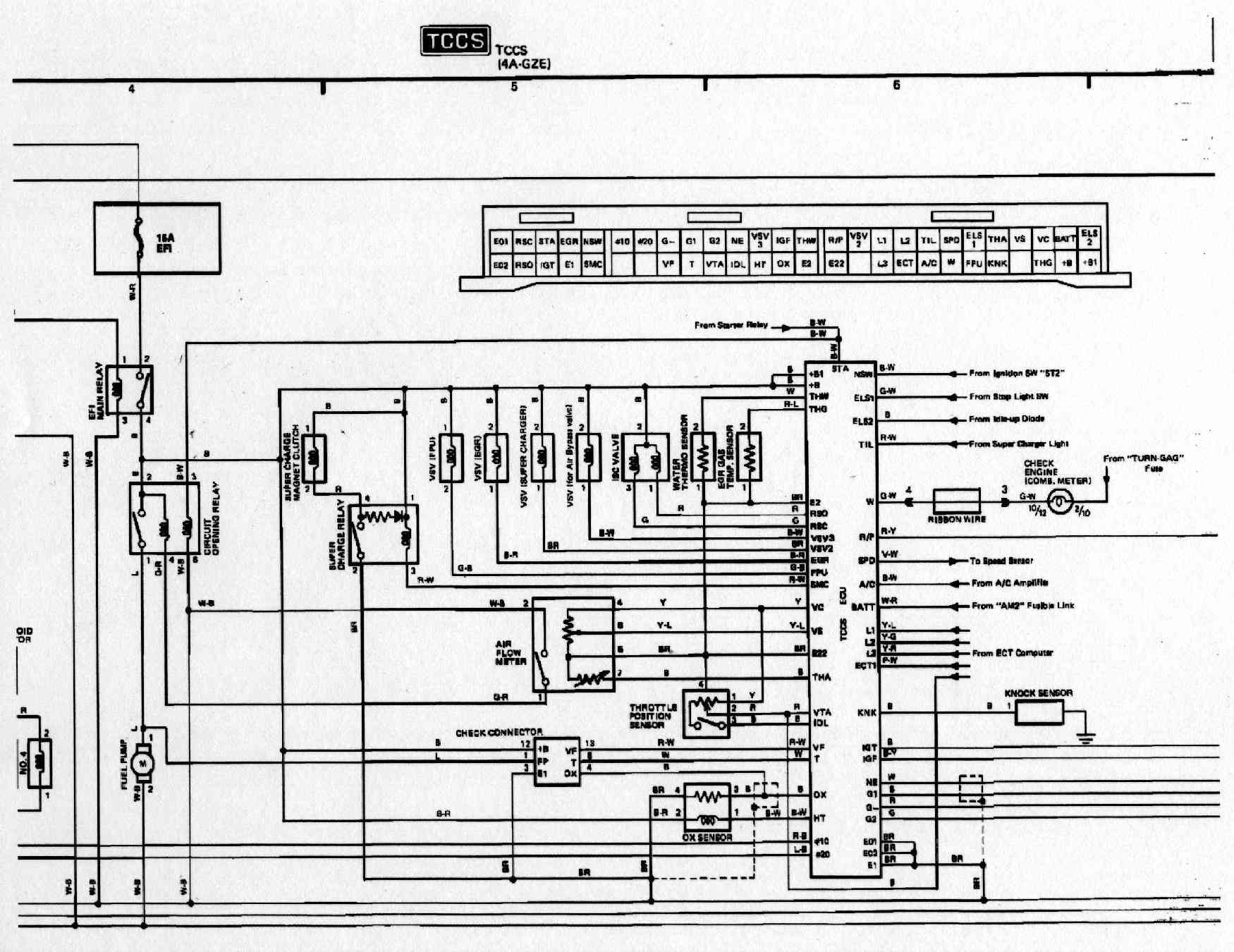

ECU Terminal Connections
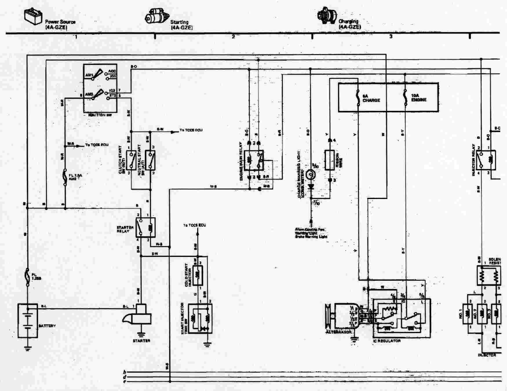
4A-GZE (USA Model AW11)
schematics contributed by Andy Karkos
Toyota 4AGZE ECU pin-outs (U.S. with AFM and distributor)
From the Toyota MR2 1988 electrical wiring diagram.

| EO2 | E01 | Earth 01, Earth 02 |
| RSO | RSC | both to ISC valve |
| IGT | STA | IGniTer, STArter signal and cold-start injector |
| E1 | EGR | Earth 1, EGR solenoid |
| SMC | NSW | Supercharger relay, Neutral switch 0r clutch switch |
| xxx | #10 | not used, Injectors 1 and 3 |
| xxx | #20 | not used, injectors 2 and 4 |
| VF | G- | Check connector, distributor pickup coil |
| T | G1 | Test pin (check connector), dist. pickup coil |
| VTA | G2 | throttle position sensor, distributor pickup coil |
| IDL | NE | Throttle position sensor, distributor pickup coil |
| HT | VS3 | O2 sensor heater, air bypass valve solenoid |
| OX | IGF | Oxygen sensor, IGnition Feedback from ignitor |
| E2 | THW | common for THW THG and AFM, THermistor Water temp |
| E22 | R/P | Same as e2, Regular/Premium switch |
| xxx | VS2 | Not used, supercharger vent solenoid |
| L3 | L1 | From ECT computer |
| ECT | L2 | From ECT computer |
| A/C | TIL | From a/c amplifier,Supercharger light |
| W | SPD | To check engine Warning light, speed sensor |
| FPU | ELS1 | Fuel Pressure Up solenoid, stop light switch |
| KNK | THA | KNocK sensor, THermistor Air temp (in afm) |
| xxx | VS | not used, AFM wiper |
| THG | VC | THermistor eGr, AFM supply voltage |
| B+ | Bat | switched +12v, constant +12v |
| +B1 | ELS2 | switched +12v, idle up diode |
