TRD Race Height Suspension
Conversion Guide
Guide by Dale of Shinkai Racing (SKR)
Edited By Moto-P
![]()
PART 1. FRONT COIL/DAMPER UNITS
Many people have been asking questions about coil/dampers for some time now. Coil/dampers are an optional upgrade for those that want to experiment with the suspension in a quest to fine tune their cars to meet their driving demands. Do you need them in the AE86. Not necessarily so, but it is a nice addition. They can be fun and dynamic.
Most of the questions have been in regard to using particular damper units and their adaptability to the AE86 strut casing. "Do you need to cut the strut?" "Where do you weld the sleeve?" And more importantly, "Why do you need to cut the strut?" All are valid questions. One will not know unless one asks. It's one thing to answer, but it's another thing to answer and provide pictures and instruction along the way. Author's disclaimer- not everything one would want to know about design and implementation will be covered here. In order to keep things simple, we will develop a set of coil/dampers in the most common fashion based on technique used by many private tuner shops in Japan.
COIL ASSEMBLY COMPONENTS

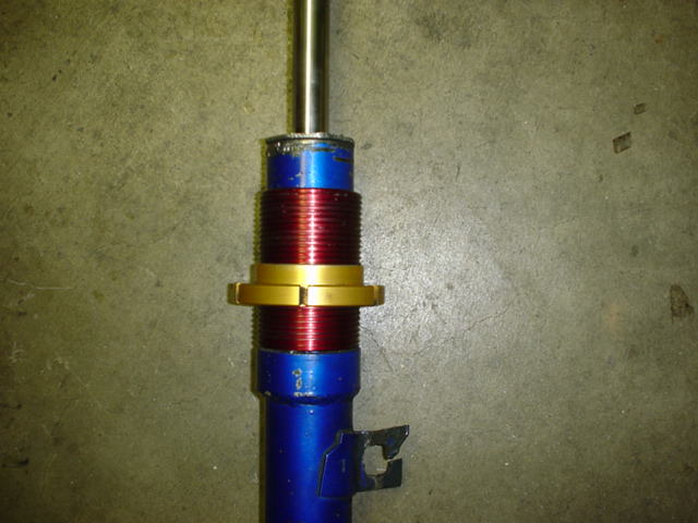
This is the Harada Shokai front coil/damper kit used to construct a fully operational coil/damper unit with the front strut casing of the AE86. As you can see, the kit consists of top cap, coil, sleeve, height adjust screw and locking screw. The picture below illustrates them more clearly.
---In the USA, similar kits are produced by Ground Control, which comes with Eibach's race bred straight coils. Moto-P's car uses the same coil over kit by Ground Control, available with different coil spring rates.
As you can see, there is nothing fancy at all about them. The coil and spring are made of hardened steel, while the top cap is made of billet hardened T-6 CNC'd aluminum with a stainless steel center insert. (anodized alloy for the Ground Control kits) The two screw pieces are also made of hardened T-6 billet aluminum. The springs come in a range of 4-12 Kg/mm. You can choose the spring down rate of your choice. Below are photos of the sleeve.


DISASSEMBLY OF THE STRUT
This photo illustrates the stock OEM strut and spring assembly. The damper next to it is a TRD piece made by Tokico for the AE92 and AE101. This is the yellow "short shock", as known by most.

Before we got to this point, we used a spring compressor to take pressure off the top cap and lower perch. This is a safety issue. PLEASE! Do not try to remove a coil that has pressure on it, no matter how docile it looks. Once it was determined that the compressors had done their job, the center nut connecting the top cap to the damper connecting shaft was removed. The shaft free-spins, so you'll need an impact wrench.
After the top cap and coil were removed, we then proceeded over to a vice to get ready to remove the retaining screw from the top of the strut casing. This big screw is the only thing that keeps the damper elements within the strut. To remove the screw, we needed a huge adjustable wrench. When the damper was safely placed into the vice, we only tightened the vice to a point that it would hold the strut while not damaging the strut casing itself nor allowing it to spin itself when pressure was applied. It took a few trial/error fittings to get to this point. Once it was locked in place, we then removed the screw. It is a wise choice to spray some sort of penetrant to aid in breaking the screw free. Some come off quite easily, while others need a little prodding. Be patient, it will come off.
Once the screw is off, do not tip the strut over, unless you like getting dampening fluid all over you and your workspace. Drain off the fluid and recycle it at a used oil disposal point. At this point, you can take some brake cleaner or dry cleaning solvent (parts washer) to remove excess grease/oil from the strut casing. It is not necessary to get too pretty at this point, for the work has only just begun. Next we will cut off the lower perch from the strut casing.
REMOVAL OF THE LOWER PERCH

This point is what I consider the most tedious and critical step- removal of the lower perch. The lower perch is where your coil sits in. Its removal is necessary to facilitate installing the coil sleeve. We'll talk about that more later on, but now, let's get prepped up for the cutting portion of this install.
As you can see in the photo above and below, I have a vice, a hand-held cutting tool with a diamond blade, as well as a vent pipe. The vent pipe will help get rid of the smoke/fumes when we get to the weld portion. Again, I ensured that the strut casing was adequately held in place without damaging it. Before any cutting work began, I made sure that I am properly equipped to perform cutting work. This means safety shoes, safety glasses, hearing protection and minimum exposed skin. Coveralls and gloves (we recommend MECHANIX) do the job. If you have short sleeves, wear a jacket. The amount of metal being removed is small in particulate, but they are red hot and can burn you, so why take chances. The method of removing the metal perch required taking bits and pieces out of it around the outer circumference and slowly working my way in towards the center. The closer I got the center where the perch is welded to the strut casing, the more care I took to not cut into the casing itself. This kind of cutting takes practice. At this point, it is more like sanding than cutting, since only very thin layers are being removed.


This is the result of after an hour's worth of labor (I take my time). The perch has been completely removed and the weld marks taken down flush. The bare metal area you see on the strut casing is where paint was removed during the cutting/sanding process. Some may ask, why didn't you cut the perch off with a cutting torch? Simple, the torch is meant for big, heavy less precise work. Also, one would risk the possibility of warpage due to dissimilar heat transfer, as well as a fire hazard (in the event your strut casing still had oil residue) and the possibility of cutting into the strut casing. This is why I didn't use a cutting torch.

 <--That's Dale :)
Notice how easily the coil sleeve slides over the strut casing. At this point, you can clean the pieces up, but then again, why would you when you are faced with welding next.
SHORTENING THE STRUT CASE TO ACCOMMODATE SHORT STROKE DAMPER
Picking up where we last left off, we were going to weld the coil sleeves, BUT as we mentioned in Club4AG, we will proceed on to do further modifications to the strut case to accommodate the short stroke dampers, whether they be TOKICO HTS, TRD race height short stroke or another model that uses short dampening. Here we go...


In order to make them, we have to reduce the overall length of the strut casing by 25 to 40mm, depending on the model of the dampers and your desired height of the car... The standard reduction is 40mm.
What better place to take that much meat out them but at the area where the original lower perch was located. In order to make the marks, we first clean the area with brake cleaner and a rag. Make sure you get the grease/dirt off as much as possible in order to lay your line down. You will need a rule measuring in metric, as well as a marking tool, preferably a china marker or grease pencil, as shown below. The rule is made out of rubberized plastic, and is made by HELIX. I chose this rule because it BENDS, allowing me to wrap it around and measure, as well as draw a straight line. Both the rule and the marker can be found at any discount store or Office Max or Office Depot. Not a lot of scratch, just $3.00 for both.
--- Another more important reason we do NOT cut it off from the top is that we need to save the threaded portion of the strut case to fit the top lock cap back in. This thread is hard to replace if damaged so please be careful in handling that area...machine shops rarely have the necessary tap to re-tap the fine thread of such large diameter.

As shown below, I have already determined that I will take 20mm form the top and the bottom of the weld line to make 40mm total. Once I have determined, the marks, I wrap the rule around the circumference of the casing in order to line everything up and to make my marks.


Now observe how the lines measure...

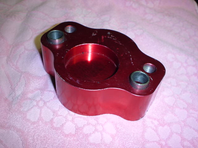
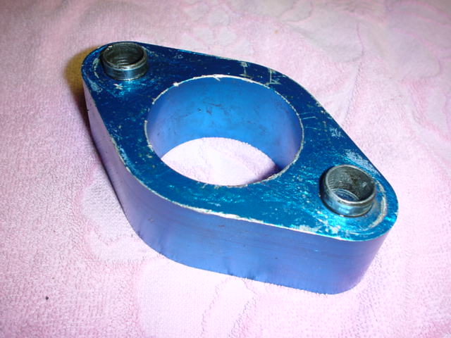
In the case of using aluminum sleeves, a pipe section cut to a ring is welded on to the case at the bottom where the sleeve must sit in order to serve as a seat for the aluminum sleeve....as aluminum rarely makes good solid weld to steel as temperature requirements for both metals are vastly different.
THE CUT...
To make the cuts, I used the same cutting wheel I used in the first part, as well as a vice to hold things stable. Again, I observed proper safety precautions and procedures- no loose-fitting clothing, safety glasses, hearing protection, hard shoes, proper tools without electrical hazards, gloves. the following are the finished product after the cutting.


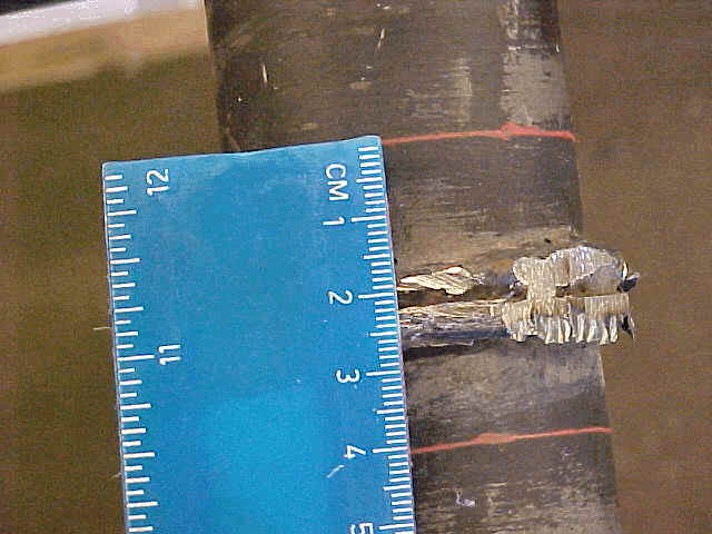
As you can tell, the cuts were made and the 40mm piece is now cut out. Looking at the 2 photos above, you can see where a file (flat on one side and curved on the other) is used to clean up the pieces, especially on the inner diameter. Just make sure you leave no burrs on the inside, for you will want the dampers to go in and out with no obstructions.


Lastly, the photo below demonstrates the strut now 40mm shorter than the OEM piece. It is not welded yet, but it is here to give you a representation of what it will look like.

Before we weld, we will ensure the trueness of the casing by using an old damper to help align the two pieces being welded. To do this, I have enlisted the help of a professional welder who helps out SKR from time to time. His name is Ben, and he looks like Billy Gibbons from ZZ TOP. Ben is a classic car guy (can you say Model T?) Anyway, I've got him convinced to do a Model T with a 4AG power plant. Should be cool!
THE WELD...

Well, here they are...

This is Ben. He does all of my welding. His forte is vintage collectibles, like Model Ts. As I said, I have him convinced to take on of SKR's blue tops and put it into a Model T.

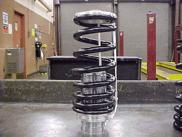
Please judge them for yourself. These pieces are well made and will not break/fall apart. SKR can make these for you for $650.00/set. Dampers are not included. With this set, you can use TOKICO 5-way adjustable, TOKICO AE92/AE101 short stroke, as well as the venerable TOKICO HTS.
Moto-P's Addendum...
WHY DO WE HAVE TO DO THIS? ITS A PAIN!!??
The following is to address the common question of "why" we need to cut (shorten) the strut case for using TRD short stroke. For those who understand it, you can skip this section and get to work...
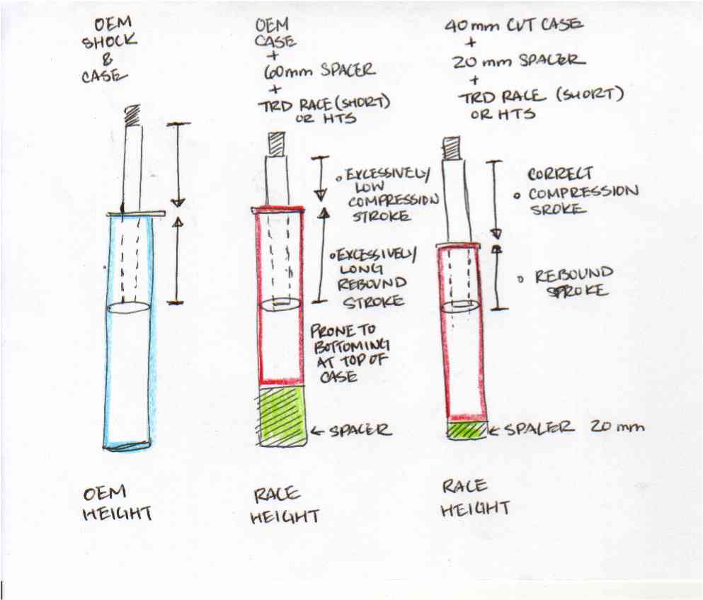
The strut case on a McPherson strut assembly like the system used on the front of the AE86 (and most other Corollas) are designed operate at a certain vehicle suspension height. Therefore the shock stroke range, compression and rebound, is optimized to the use of standard OEM height strut. The normal stroke range of the AE86 is 186 mm. Now, by using the TRD short stroke "race" strut, the overall suspension travel is reduced to 165 mm, a reduction of 21mm. Add to this the height change by using the short race springs is approximately 30 to 60 mm, depending on your preferred height adjustment of the coil over unit. By installing this in a standard length case will result in a optimum stoke range be vastly out of position. Moreover, the strut case will hit the top mount and prevent the full stroke from occurring, and the front suspension will be left with virtually no stroke on the compression side.
Reason having been explained TRD's decision was to make the strut cartridge 20mm shorter than necessary to provide transferability to other models such as KP61 and AE92. This design translates to the TRD short stroke unit being 62 mm shorter than comparable OEM strut cartridge. (This may vary by model and other comparable shocks such as the Tokico HTS, which are 60 mm shorter) In any case, we must do out subtraction here... So to put a TRD short stroke cartridge into a 40 mm cut strut case, we must also use a spacer at the bottom of the cartridge to place the shock into the optimum stroke location, and in this case the spacer would be 62 mm - 40mm = 22mm, or 22 mm of spacer must be provided to lock the cartridge into correct location.
By careful calculations, you will provide the designed outcome for the TRD short stroke shocks which are in balance with the rear short stroke spring/ shock combination. The rear system is not a height adjustable design, so front strut assembly must be matched to compensate...and this is where the coil-over conversion becomes handy in taking up slight construction error and to fine tune the fore-aft distribution of weight and overall height.
Finally, I'd like to add that fact that.... the suspension in any automobile is a critical part that supports the car and is holding the tire in place. As you can imagine, it is VERY dangerous to have these parts fail, even when the car is stationary... So please use HUGE caution when working with these items and during the design process. Its not a bad idea to go to a junk yard to buy spare set of parts just to practice on, or even to use as spares if there are any mistakes or faults in the final project. Its much more comforting and easy to do so, rather than hunting around desperately for parts in a hurry.
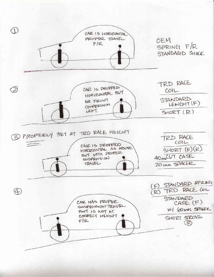
OK, and last item here is a few drawing I had done for some BBS questions in the past...please ignore the fact that the drawing is rather crude, it's for guiding you with pictures to get a rough mental picture of purpose and concept of making the conversion...of course the pictures are not to scale so don't be alarmed if your strut case does not look this way... No, the cartridge is not warped and do not have eyes...(^^)
(Click Photo to enlarge)

Now here's the last advice,
Since you will be taking your suspension apart down to the last nut, I do suggest that you get all your other modifications ready to install at this time. For example the following things can be added as well to make life easier, so as not to repeat the disassembly...
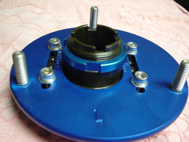
Pillow Ball Upper Mounts
Pillow ball upper mounts solidify your chassis against a strut tower bar and gives added steering response, greater rigidity, alignment integrity, and with camber adjustment feature, you can alter the camber alignment to address your turn-in characteristics and tire wear. It is highly recommended for anyone who drives agressively camber adjustemtn can offer significant changes in initial cornering response and overall cornering force. (if you know what you are doing...) Some camber upper mounts also have provisions for strut height adjustent to compliment your coil-over to make it stroke adjustable. Cusco height adjustable shown is now discontinued but Project Mu still has them.
 Cusco Upper mount with camber and height adjustment
 Cusco upper mount with camber adjustment
Roll Center Adjusters
Roll Center Adjusters, are also highly recommended on cars using the "Short Stroke suspension" much like the one mentioned here as shortened strut case alters the lower arm static angles unfavorably. This unit is used to compensate for the front lower arm's position and restore the proper geometry for the AE86 suspension.
Some have negative offset built in so that it can be used in conjunction with upper mount to give greater flexibility to track width as well as camber alignment.
 Revolver's Negative Camber offset Roll Center Adjusters
 Cusco Roll Center adjusters
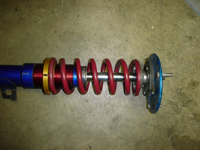
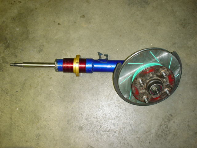
Photo of a completed strut using Ground Control Sleeve, OEM converted strut, HTS cartridge damper, Cusco Upper mount. I have painted the converted OEM strut Cusco-like Blue to match the Cusco upper mount....OEM strut conversion do not have to be ugly, right?