
ECU Terminal Diagram
USA AE86 16V 4A-GE
Submitted By Richard White
4A-GE Electronic Control Unit (ECU), 8408~8708 Corolla GTS US Market, Toyota P/N 89661-12092-84
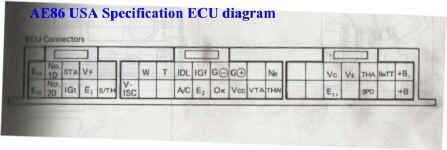
Per Electrical Manual (E21 and E2 incorrect in the Factory USA electrical manual)
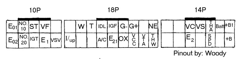
Correct pin diagram as informed by Woody (tested)

Factory Repair Manual, pins listed correctly. V Connector
|
Pin No. |
Symbol |
Color |
Terminal |
|
1 |
|||
|
2 |
VF |
R-L |
Check connector |
|
3 |
ST (STA) |
B-W |
Starter switch |
|
4 |
No. 10 |
Y |
No. 3, 4 injector |
|
5 |
E01 |
BR |
Engine ground (Power) |
|
6 |
VSV-(S/TH) |
R-W |
Vacuum switching valve (S/TH) |
|
7 |
E1 |
BR |
Engine ground |
|
8 |
IGT |
B |
Igniter |
|
9 |
No. 20 |
G |
No. 1, 2 injector |
|
10 |
E02 |
BR |
Engine ground (Power) |
|
Pin No. |
Symbol |
Color |
Terminal |
|
1 |
NE |
R |
Engine revolution sensor |
|
2 |
|||
|
3 |
G+ |
B |
Engine revolution sensor |
|
4 |
G- |
W |
Engine revolution sensor |
|
5 |
IGF |
B-Y |
Igniter |
|
6 |
IDL |
L |
Throttle sensor |
|
7 |
T |
LG-B |
Check connector |
|
8 |
WAN |
G-W |
Warning light |
|
9 |
|||
|
10 |
THW |
G |
Water temp. sensor |
|
11 |
VTA |
R |
Throttle sensor |
|
12 |
VCC |
L-R |
Throttle sensor |
|
13 |
OX |
B |
Oxygen sensor |
|
14 |
E21 |
BR |
Sensor Earth |
|
15 |
A/C |
B-W |
A/C Magnet clutch |
|
16 |
|||
|
17 |
|||
|
18 |
I/UP (VISC) |
B |
Vacuum switching valve [Idle up] |
|
Pin No. |
Symbol |
Color |
Terminal |
|
1 |
+B1 |
B-R |
Main relay |
|
2 |
BaTT |
R-W |
Battery |
|
3 |
THA |
Y |
Inlet air temp. sensor |
|
4 |
VS |
Y-L |
Air flow meter |
|
5 |
VC |
L-R |
Air flow meter |
|
6 |
|||
|
7 |
|||
|
8 |
+B |
B-R |
Main relay |
|
9 |
|||
|
10 |
SPD |
L-W |
Speedometer |
|
11 |
|||
|
12 |
E2 |
B-R |
Sensor earth |
|
13 |
|||
|
14 |

Farewell to the Generation 1 Toyota 86, and Subaru BRZ, as well as Lexus GS.
Toyota announced that the Lexus GS will end production soon in August, and Subaru will produce the last 1st generation Toyota 86 and Subaru BRZ in July, May for European ...


TOM'S KP47 Starlet, that's Tachi-Oiwa Motorsports
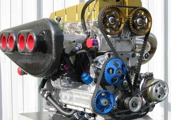
The KP47 Toyota Starlet here was carefully built and assembled by Tachi-Oiwa Motorsports. That's TOM's Racing, for most of you who've seen their logos on ...Is this the end of the 4A-GE? 4AG and Hasselgren Engineering
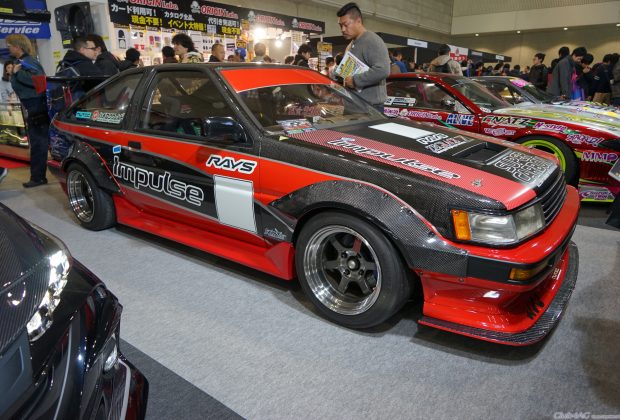
Is this the end of the 4A-G? The last 16 valve 4A-G was produced in 1993; the last 20 valve in 2002. Moreover, the ...Toresor Impulse Full Carbon Fiber AE86 at Tokyo Auto Salon 2019
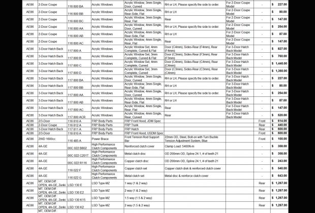
At the Tokyo Auto Salon this year 2019, a small booth by Impulse (Japan) had a neat project car for AE86 owners. A FULL Carbon ...AE86 - TOYOTA Corolla GT-S / LEVIN / TRUENO - CUSCO PARTS LISTING
AE86 - TOYOTA Corolla GT-S / LEVIN / TRUENO - CUSCO PARTS LISTING *some of the items have been discontinued, however left in there as ...

Load More