Interesting topic, and one that probably warrants its own thread. But we
will leave it here for now and see what develops

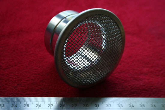
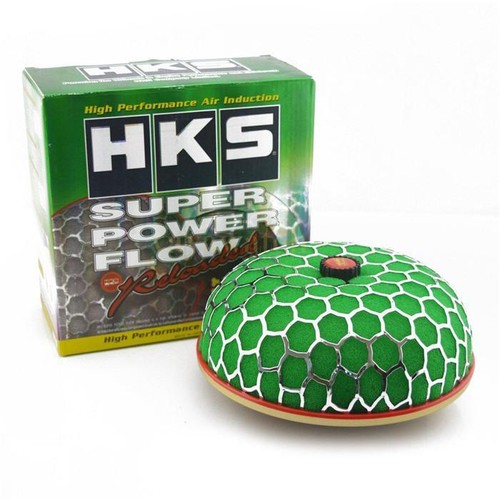
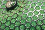
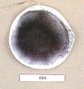
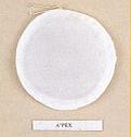
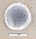
Here is a picture showing the construction of an Apexi filter...
.jpg)
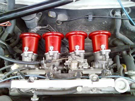
As you can see the filter has a bellmouth built-in to improve flow from the
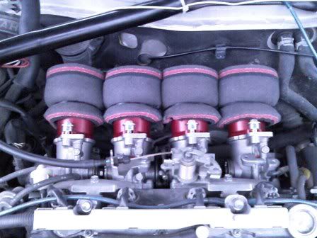
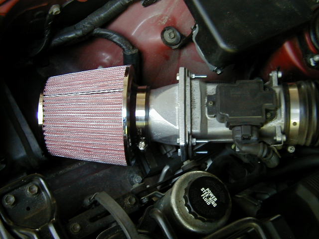
filter to the intake. By the look of your pic, you have essentially installed
a filter with a bellmouth on top of a second bellmouth. In so doing you have
created a "step" which will interrupt the airflow and create turbulence. The
good thing about your setup is that you have used an oversize filter, so your
resistance to flow will be low. The lower velocity over the "step" will also
reduce the impact of the turbulance created.
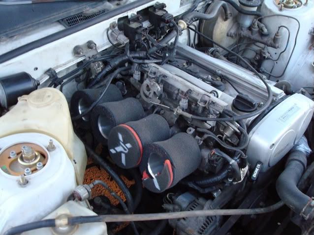
Unfortunately, you also appear to have an abrupt change of section where
the round throat of the bellmoth meets the square opening for the AFM.
This will cause a lot of turbulence and disruption to the smooth airflow from
the bellmouth. I can't say what the overall result would be... better or worse
than a correctly sized filter and matching intake ?? However, I suspect worse.
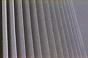
In airflow engineering the square to round transition is one of the basic
components when connecting ducting together...

Soory about the big pic, but this illustrates perfectly how the change from
square to round is designed to avoid any abrupt changes to the direction or
velocity of the air. The transition should be as long as space allows, and the
included angle between opposite side should be as small as possible, preferably
less than 15 degrees.


The idea is to avoid flow separation where the airflow pulls away from the
wall of the duct or pipe, creating an area of turbulence. Turbulence absorbs
energy from the flow and in so doing reduces the net flow rate. Therefore all
changes of direction or cross section should be as smooth and gradual as
possible for best flow.

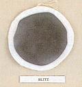
The design of a bellmouth should channel air down a tube of decreasing
diameter with the curve shaped to avoid flow separation at the entrance,
and a smooth transition to the intake. The above pic shows a bellmouth
with a parabolic curve which is said to be the most efficient. If the bellmouth
is to match with a tapered bore ITB (20V ITB's for example) the exit tube
should also have a similar taper to the ITB throat, to avoid an abrupt change
in angle at the entrance to the ITB.
More info than you need, but it is useful to understand what you need to
do to get the best airflow with the lowest pressure drop

Cheers... jondee86


 ;
;
 ;
;
 ;
;
 ;
;


