ae86 4agze supercharged help please!!
-
therealkillingdonuts
- Posts: 3
- Joined: Tue Oct 13, 2015 5:00 am
ae86 4agze supercharged help please!!
so I've been owning my 86 for about 6 months and I've been having this one problem that's really bothering me I have the usdm cluster where the rpm's redline is about at 7.5rpms and mine only gets to 3.5rpms that's as highest it'll go, basicly my redline is at 3.5rpm can't sort that out any help will do.

Re: ae86 4agze supercharged help please!!
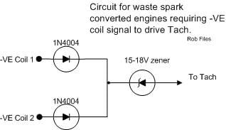
If you are running GZE coilpacks, and only taking a signal off one, then
you will only get 50% of the real engine speed. You need to take the signal
off both coilpacks with a circuit something like this....
Cheers... jondee86
you will only get 50% of the real engine speed. You need to take the signal
off both coilpacks with a circuit something like this....
Cheers... jondee86
The reasonable man adapts himself to the world; the unreasonable one
persists in trying to adapt the world to himself. Therefore, all progress
depends on the unreasonable man.
persists in trying to adapt the world to himself. Therefore, all progress
depends on the unreasonable man.
-
therealkillingdonuts
- Posts: 3
- Joined: Tue Oct 13, 2015 5:00 am
Re: ae86 4agze supercharged help please!!
problem is the first owner built this and previous owner had no idea either so I wouldn't know where to start haha
- Attachments
-
- that's what I have
- image.jpg (74.5 KiB) Viewed 6125 times
Re: ae86 4agze supercharged help please!!
Then, you are gonna need to get someone who knows about electrical wiring
on cars to do this for you. The circuit above shows a connection to the negative
side of each coil primary. There is a diode in each connection and after they
join together, a zenner diode that just lets the flyback voltage spike from each
coil pass thru. The voltage spike is what drives the tacho.
The coil packs are the black things at the back of the engine on the far end of
the red wires. Each coil pack has a small green 2-pin plug on the end under the
red wires, and a black clip with two wires that pushes onto the green plug. The
wires from one clip should be tan and black, and from the other tan and green.
The tan wires get 12V when the key is ON, and the green and black run to the
igniter which grounds them alternately to fire the coils.

I am gonna assume that you have the factory GZE igniter and ECU, so one of the
coil negative wires (black or green) should already be tapped off and connected
to the tacho to get it to run at half revs. What needs to happen is a tapping
from the other coil negative wire, then add the diodes and splice into the
existing tacho wire. Sounds complicated but it will be a piece of cake to an
auto electrician or anyone who has a bit of experience with wiring cars.
Cheers... jondee86
on cars to do this for you. The circuit above shows a connection to the negative
side of each coil primary. There is a diode in each connection and after they
join together, a zenner diode that just lets the flyback voltage spike from each
coil pass thru. The voltage spike is what drives the tacho.
The coil packs are the black things at the back of the engine on the far end of
the red wires. Each coil pack has a small green 2-pin plug on the end under the
red wires, and a black clip with two wires that pushes onto the green plug. The
wires from one clip should be tan and black, and from the other tan and green.
The tan wires get 12V when the key is ON, and the green and black run to the
igniter which grounds them alternately to fire the coils.
I am gonna assume that you have the factory GZE igniter and ECU, so one of the
coil negative wires (black or green) should already be tapped off and connected
to the tacho to get it to run at half revs. What needs to happen is a tapping
from the other coil negative wire, then add the diodes and splice into the
existing tacho wire. Sounds complicated but it will be a piece of cake to an
auto electrician or anyone who has a bit of experience with wiring cars.
Cheers... jondee86
The reasonable man adapts himself to the world; the unreasonable one
persists in trying to adapt the world to himself. Therefore, all progress
depends on the unreasonable man.
persists in trying to adapt the world to himself. Therefore, all progress
depends on the unreasonable man.
Re: ae86 4agze supercharged help please!!
Online somewhere there is a schematic on
Replacing iirc 2 resistors and a capacitor in the tach itself. About 2$ in parts.it is easy to do. Unfortunately that bookmark came and went with my last desktop. Sorry
Replacing iirc 2 resistors and a capacitor in the tach itself. About 2$ in parts.it is easy to do. Unfortunately that bookmark came and went with my last desktop. Sorry
Shake my head... all my settings got reset.... whats happenning to club4ag's quality?
Re: ae86 4agze supercharged help please!!
I found that using the method jonndee86 suggested caused a jumpy rev clock needle any time there was an extra electrical load turned on, turn signals etc.
I then changed 2 resistors and a capacitor in the rev clock circuit board and the needle is steady.
Found this:
http://forums.club4ag.com/zerothread?id=68162
I then changed 2 resistors and a capacitor in the rev clock circuit board and the needle is steady.
Found this:
http://forums.club4ag.com/zerothread?id=68162
-
Jeff Lange
- Club4AG Enthusiast
- Posts: 91
- Joined: Wed Jan 09, 2013 4:04 pm
Re: ae86 4agze supercharged help please!!
Changing the resistors on the tach PCB is the best method for the DLI ignition on the 4A-GZE.
Jeff
Jeff