Megasquirt/7AGE/Custom harness questions (Wiring Guru help!)
Posted: Sat Nov 21, 2015 2:56 pm
So I've finally got the engine into the car and it's time to start making the custom engine harness that won't make the bay look so hideous.
I've been doing a lot of research the last few weeks and I have a good grasp on what I need to do. Just need some feedback from the wiring pros in-case there is something I missed. I will be running a Gen 2 Megasquirt PNP, I have an extra harness to get ECU connectors from and I've orderd 16 Bosch style plugs and pins. I've also acquired 13 colors of TXL wiring to hopefully knock this out.
I have color coded the schematics to show what will need to be ran, spliced and what is existing.
Blue = Existing
Orange = Splice
Green = New wire to be ran
**You may also note that some of the wires/connectors from the 3rd "A" Connector from the ECU not being highlighted. I do not plan on messing with this group of wires since they do not run through the engine harness.**
Here are my questions.
1. MS does not show to need the ST wire, this seems odd to me but I'm assuming it was just a signal for the factory ECU. Is this correct?
2. Same as above question but with the OX sensor. Since I am installing a wideband I do not need it, correct? I will be wiring it into the DB15 connector.
3. Megasquirt says the following on deleting the AFM. Do I show the correct wires spliced on the diagram? (I don't think it is due to it not having a dash between the BR, or is maybe one of the B-R wires going to the EFI Main Relay?)
"To control the fuel pump, you need to do two things. You need to run a jumper wire between two wires at the AFM first. The GRN/RED wire and the BLUE/RED Wire. Connect these together."
4. On wires E21 & THW they show to connect together (E21 being a ground and THW being the ground side of the sensor). Am I wrong or does this mean I need the single prong connector for the dash gauge and another sensor for the MS? I believe this to be the case since the single prong sensor will not have a ground going to it.
5. All the ground wires used to run to the intake of the engine, I would like to move them to the block so they are hidden. This will be fine as long as I have a ground wire going from the engine to the body of the car correct?
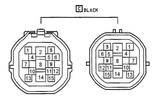
6. Does anyone have a higher resolution of the schematics I have attached below, or know where they have come from? I can't make out half the letters/numbers on it and it would help tremendously with figuring out what I do and do not need for the C plug.
I have also attached the helpful printouts from the MS website concerning what needs to be kept and deleted.
http://i.imgur.com/Cdr8pi8.jpg
http://i.imgur.com/nf51h1J.jpg
http://i.imgur.com/hjeCD9x.jpg
Sorry for just image links, no hosting sites offer re-sizing anymore and this site has a ridiculous limit on size.
I've been doing a lot of research the last few weeks and I have a good grasp on what I need to do. Just need some feedback from the wiring pros in-case there is something I missed. I will be running a Gen 2 Megasquirt PNP, I have an extra harness to get ECU connectors from and I've orderd 16 Bosch style plugs and pins. I've also acquired 13 colors of TXL wiring to hopefully knock this out.
I have color coded the schematics to show what will need to be ran, spliced and what is existing.
Blue = Existing
Orange = Splice
Green = New wire to be ran
**You may also note that some of the wires/connectors from the 3rd "A" Connector from the ECU not being highlighted. I do not plan on messing with this group of wires since they do not run through the engine harness.**
Here are my questions.
1. MS does not show to need the ST wire, this seems odd to me but I'm assuming it was just a signal for the factory ECU. Is this correct?
2. Same as above question but with the OX sensor. Since I am installing a wideband I do not need it, correct? I will be wiring it into the DB15 connector.
3. Megasquirt says the following on deleting the AFM. Do I show the correct wires spliced on the diagram? (I don't think it is due to it not having a dash between the BR, or is maybe one of the B-R wires going to the EFI Main Relay?)
"To control the fuel pump, you need to do two things. You need to run a jumper wire between two wires at the AFM first. The GRN/RED wire and the BLUE/RED Wire. Connect these together."
4. On wires E21 & THW they show to connect together (E21 being a ground and THW being the ground side of the sensor). Am I wrong or does this mean I need the single prong connector for the dash gauge and another sensor for the MS? I believe this to be the case since the single prong sensor will not have a ground going to it.
5. All the ground wires used to run to the intake of the engine, I would like to move them to the block so they are hidden. This will be fine as long as I have a ground wire going from the engine to the body of the car correct?
6. Does anyone have a higher resolution of the schematics I have attached below, or know where they have come from? I can't make out half the letters/numbers on it and it would help tremendously with figuring out what I do and do not need for the C plug.
I have also attached the helpful printouts from the MS website concerning what needs to be kept and deleted.
http://i.imgur.com/Cdr8pi8.jpg
http://i.imgur.com/nf51h1J.jpg
http://i.imgur.com/hjeCD9x.jpg
Sorry for just image links, no hosting sites offer re-sizing anymore and this site has a ridiculous limit on size.

