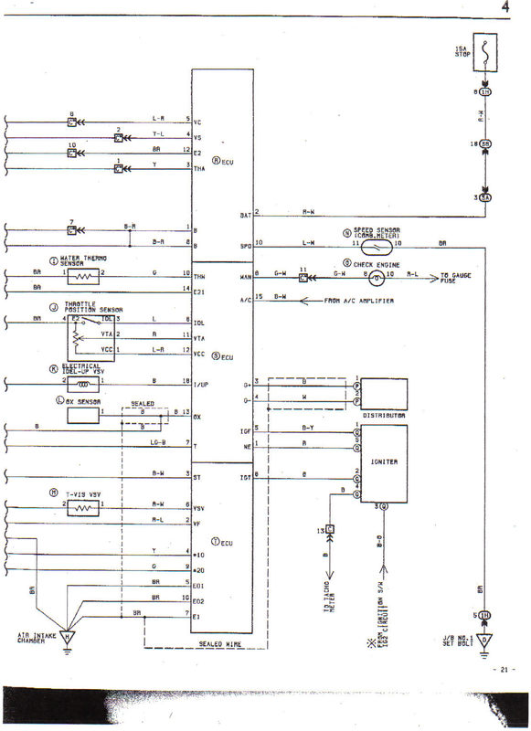
ECU Terminal Diagram
USA AE86 16V 4A-GE
Submitted By Richard White
4A-GE Electronic Control Unit (ECU), 8408~8708 Corolla GTS US Market, Toyota P/N 89661-12092-84
Per Electrical Manual (E21 and E2 incorrect in the Factory USA electrical manual)
Correct pin diagram as informed by Woody (tested)
Factory Repair Manual, pins listed correctly.
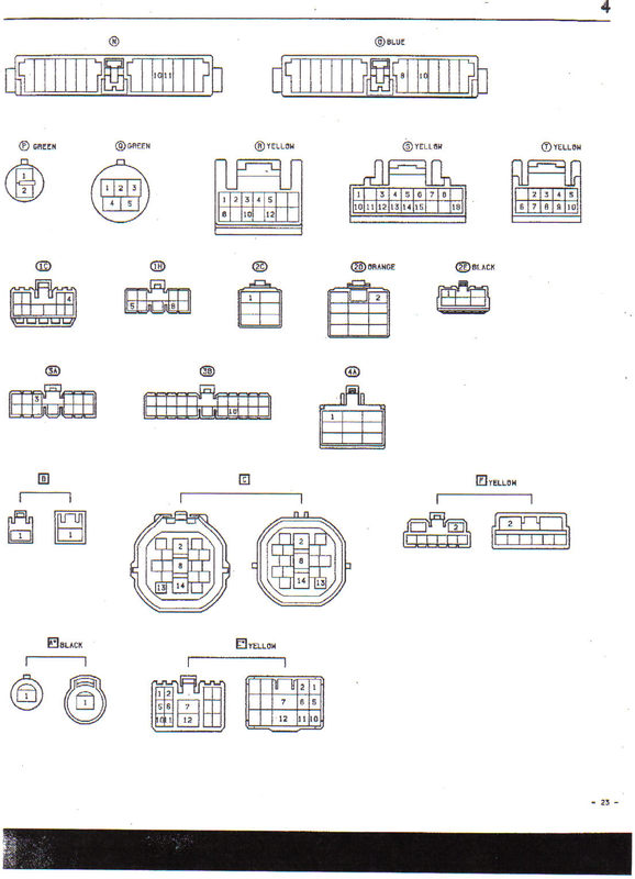
V Connector
| Pin No. | Symbol | Color | Terminal |
| 1 | |||
| 2 | VF | R-L | Check connector |
| 3 | ST (STA) | B-W | Starter switch |
| 4 | No. 10 | Y | No. 3, 4 injector |
| 5 | E01 | BR | Engine ground (Power) |
| 6 | VSV-(S/TH) | R-W | Vacuum switching valve (S/TH) |
| 7 | E1 | BR | Engine ground |
| 8 | IGT | B | Igniter |
| 9 | No. 20 | G | No. 1, 2 injector |
| 10 | E02 | BR | Engine ground (Power) |
U Connector
| Pin No. | Symbol | Color | Terminal |
| 1 | NE | R | Engine revolution sensor |
| 2 | |||
| 3 | G+ | B | Engine revolution sensor |
| 4 | G- | W | Engine revolution sensor |
| 5 | IGF | B-Y | Igniter |
| 6 | IDL | L | Throttle sensor |
| 7 | T | LG-B | Check connector |
| 8 | WAN | G-W | Warning light |
| 9 | |||
| 10 | THW | G | Water temp. sensor |
| 11 | VTA | R | Throttle sensor |
| 12 | VCC | L-R | Throttle sensor |
| 13 | OX | B | Oxygen sensor |
| 14 | E21 | BR | Sensor Earth |
| 15 | A/C | B-W | A/C Magnet clutch |
| 16 | |||
| 17 | |||
| 18 | I/UP (VISC) | B | Vacuum switching valve [Idle up] |
T Connector
| Pin No. | Symbol | Color | Terminal |
| 1 | +B1 | B-R | Main relay |
| 2 | BaTT | R-W | Battery |
| 3 | THA | Y | Inlet air temp. sensor |
| 4 | VS | Y-L | Air flow meter |
| 5 | VC | L-R | Air flow meter |
| 6 | |||
| 7 | |||
| 8 | +B | B-R | Main relay |
| 9 | |||
| 10 | SPD | L-W | Speedometer |
| 11 | |||
| 12 | E2 | B-R | Sensor earth |
| 13 | |||
| 14 |
Source: 1985 Toyota Corolla FR Repair Manual